- Progressive dynamics power converter wiring diagram how to#
- Progressive dynamics power converter wiring diagram manuals#
- Progressive dynamics power converter wiring diagram generator#
- Progressive dynamics power converter wiring diagram manual#
- Progressive dynamics power converter wiring diagram tv#
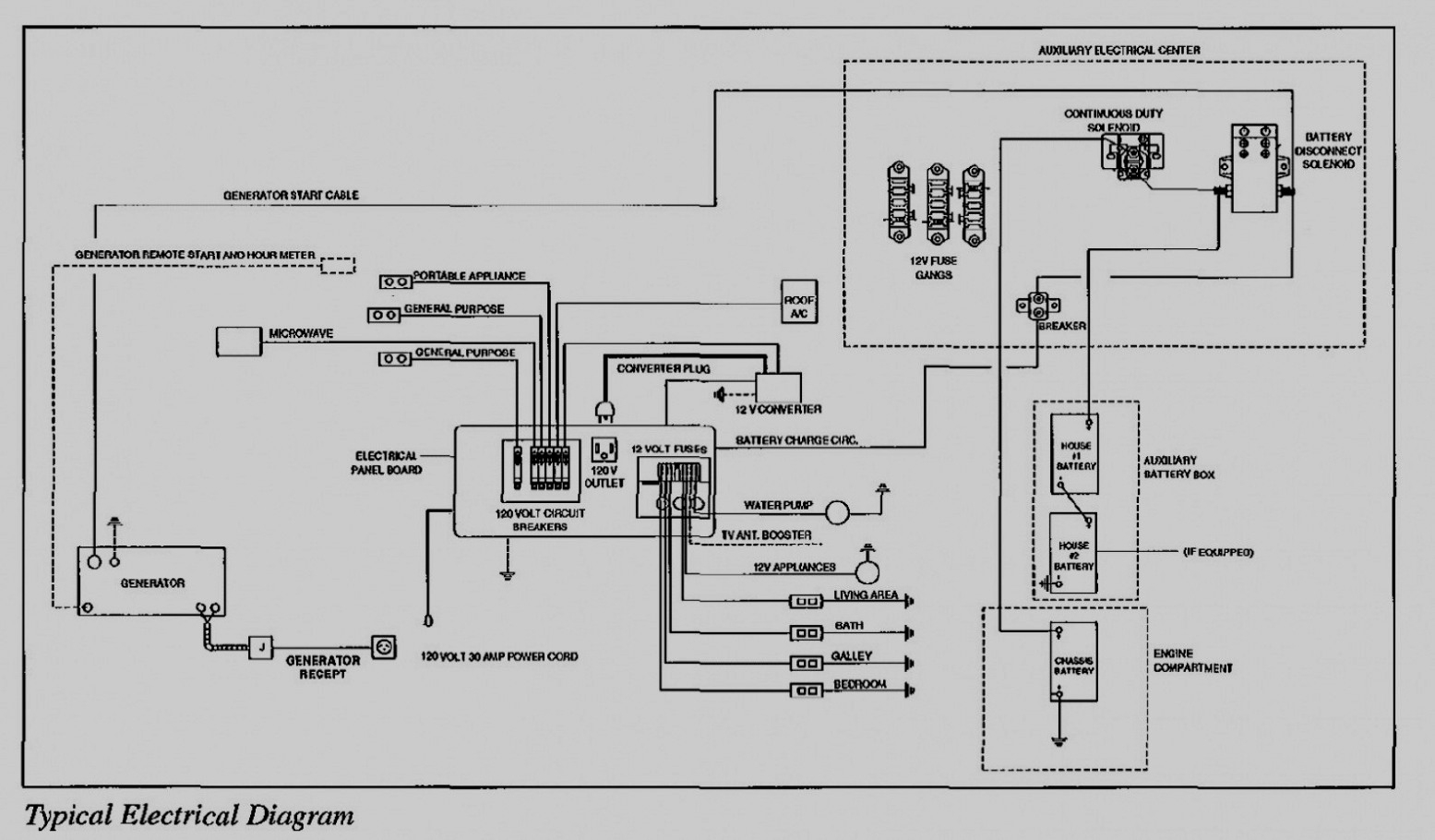
From this detailing, the viewer can identify what and where every connection will be made and how they work in connection with each other. From here, the perspective will then move upward towards the junction hub where the circuit becomes most operational. The way to start off is by identifying the source of electricity, normally stated at the very bottom of the diagram. However, with a bit of patient observation and guidance, one can eventually learn how such schematics work. The sheer complexity of such diagrams can make it intimidating for a beginner to read with total understanding.
Progressive dynamics power converter wiring diagram how to#
How to Read an RV Converter Charger Wiring Diagram By regulating abilities and power output, this setup can be an increasingly important factor in preventing any unreliable readings or inconsistencies to ensure the most appropriate setting for the RV system. It is in large part due to the extra safety measures that need to be taken while designing such a system. Especially when it comes to a wiring diagram of an RV’s converter charger, these vital essentials become even more important. To get the best optimal electrical performance, astute planning and well-thought-out designs are aspects one should always bear in mind. When talking about wiring diagrams, there is bound to be a deep dive into the intricacies involved.

Note that the DC power for the Isolated Circuits is always coming directly from the battery or the charging circuit when 120 VAC power is applied to the RV (green arrows).Exploring the Exacting Requirements for an RV Converter Charger Wiring Diagram This action also disconnects the RV battery from the branch circuits and places it on charge (blue arrows). Now the converter feeds DC Power to the branch circuits (red arrows). This DC power is also fed to the Relay Coil, which in turn pulls down the center arm of the Relay so that it makes contact with the lower N.O.

It is then fed through the Diode Rectifiers, which convert this AC Voltage to 13.8 VDC. The Transformer reduces the 120 VAC down to 13.8 VAC (Alternating Current).
Progressive dynamics power converter wiring diagram tv#
The Isolated Circuits for the Radio, TV or Stereo are connected directly to the battery positive terminal. See figure 2 below for operation when AC power is applied. The RV battery is supplying 12-volt power (Red Arrows ) to the RV branch circuits through the N.C. This resistor limits the amount of charging current that can be delivered to the battery. It is turned ON when the battery needs charging current and is turned OFF, when the circuit board senses the battery is charged. This is basically an electronic switch that is controlled by the circuit board.

Senses the battery voltage and then provides a signal to the SCR (Silicon Controlled Rectifier) to turn it ON, which in turn supplies charging current to the RV Battery.
Progressive dynamics power converter wiring diagram generator#
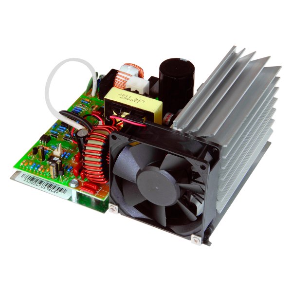
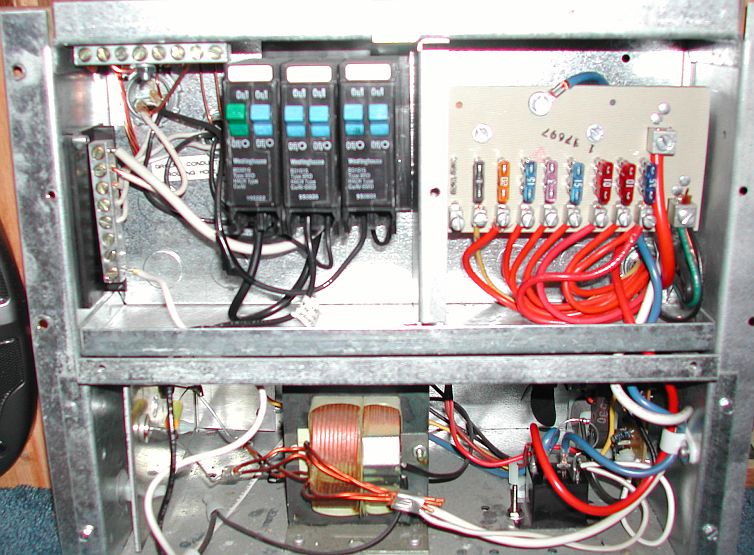
Reduces the 120 VAC from the Shore Power or Generator down to approximately 13.8 Volts AC (Alternating Current) at its secondary output.Ĭonverts the 13.8 Volts AC from the Transformer secondary output to approximately 13.8 Volts DC (Direct Current).Īutomatically disconnects the RV Battery from the 12-volt RV circuits and then connects the 13.8-volt power to the RV 12-volt circuits when Shore Power is connected to the RV.
Progressive dynamics power converter wiring diagram manual#
Power Converter Owners Manual PD684 and PD685 They do however still have some parts available for sale ( PD Parts) Unfortunately they will no longer be able to provide support for these models.

Progressive dynamics power converter wiring diagram manuals#
They are providing customers with owners manuals and troubleshooting information for the discontinued models. Progressive Dynamics is discontinuing support for these older products. Progressive Dynamics Discontinued Transfer Switchesĭuring the 1970's Winnebago used Progrssive Dynamics Power Converters and Electrical Control Centers. Dave's Place - RV Electrical Systems Dave's Place


 0 kommentar(er)
